Brute Forcing TOTP Multi-Factor Authentication is Surprisingly Realistic
August 23, 2021•2,365 words
by Oscar Brolin
By default, Microsoft BitLocker protected OS drives can be accessed by sniffing the LPC bus, retrieving the volume master key when it’s returned by the TPM, and using the retrieved VMK to decrypt the protected drive. This post will look at extracting the clear-text key from a TPM chip by sniffing the LPC bus, either with a logic analyzer or a cheap FPGA board. This post demonstrates the attack against an HP laptop logic board using a TPM1.2 chip and a Surface Pro 3 using a TPM2.0 chip. From bus wiring through to volume decryption. Source code included.
This project kicked off for me when Hector Martin (@marcan) mentioned they were able to sniff the BitLocker VMK straight off the LPC bus. Hector used an FPGA to sniff the bus for a TPM1.2 chip; I wanted to see if I could achieve the same thing with a cheapie off-the-shelf logic analyzer and attempt the attack against a TPM2.0 chip. If you’re just interested in the practical attack, then I suggest skipping to the TPM2.0 section.
TLDR: You can sniff BitLocker keys in the default config, from either a TPM1.2 or TPM2.0 device, using a dirt cheap FPGA (~$40NZD) and now publicly available code, or with a sufficiently fancy logic analyzer. After sniffing, you can decrypt the drive. Don’t want to be vulnerable to this? Enable additional pre-boot authentication.
BitLocker 101
Windows uses BitLocker to encrypt drives. The data is encrypted using the Full Volume Encryption Key (FVEK). The FVEK is in turn encrypted with the Volume Master Key (VMK). The VMK is encrypted by multiple protectors. For example, in the default configuration there are two protectors. One is the TPM, the other is the Recovery Key. All of this exist so that if an attacker has physical access to the device, they can’t boot the laptop into a Linux live distro (or remove the drive) and access your data.
When you enable BitLocker in its default configuration, no additional user interaction is required at boot. This is due to the TPM only being used to decrypt the VMK. The idea behind this is that if the laptop is stolen, and the attacker does not know your login password, they can not pull the drive and read the contents. Any modifications to the bios or boot loader code should change the PCR values, and the TPM will not unseal the VMK.
As the decryption happens automatically, if we can sniff the VMK as its being returned by the TPM then we can enter that information into any number of BitLocker libraries and decrypt the drive.
Trusted Platform Modules
This post wont be going into much detail on TPM fundamentals. If you’re not familiar with what a TPM does, Microsoft has some good docs on TPM fundamentals. The general gist here is that the TPM wont unseal keys unless its in an expected boot state (the PCR registers have a specific set of values in them). That’s why you can’t boot off an Ubuntu live image and just smash an unseal command at the TPM.
The TPM hangs off the LPC, SPI or I2C bus. Check the data sheet for your specific chip. This blog post is looking at the LPC bus, specifically. I’ve added a link to the TPM client spec in the reading section at the end of this post. For SPI or I2C attacks, I’d start with a logic analyzer and go from there.
TPM1.2
We’ll start with the TPM1.2 device, and aim to replicate @maracan’s work.
Wiring
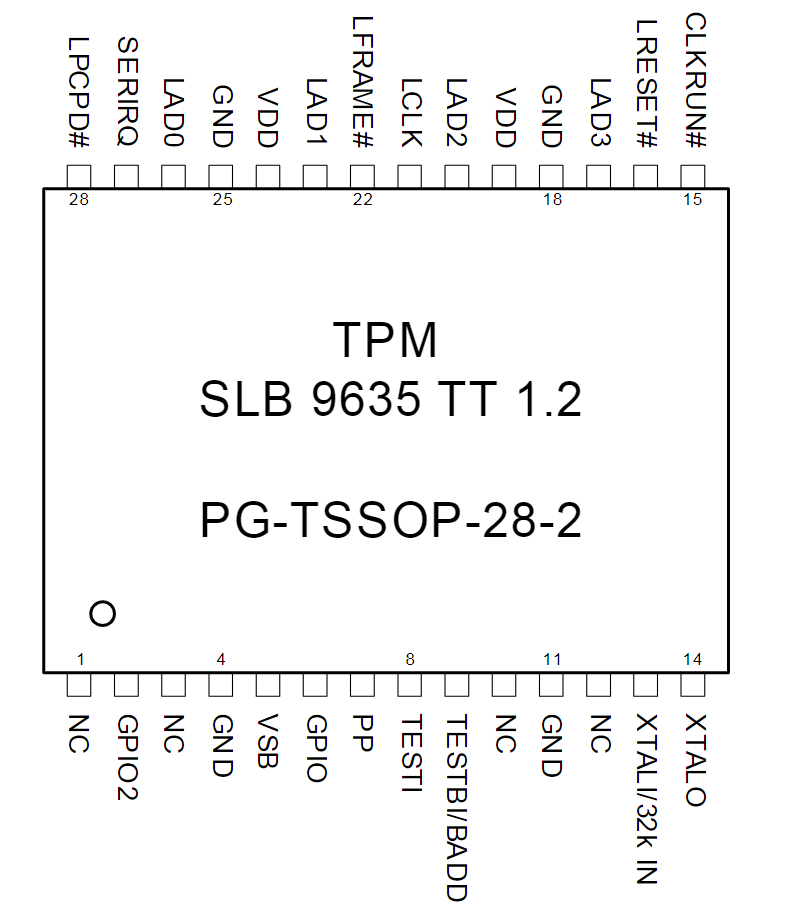
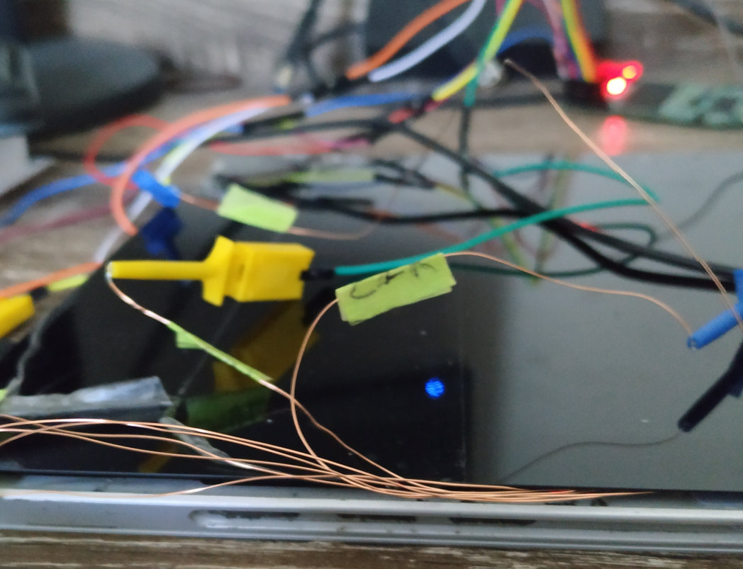
The board I tested on has an Infineon SLB96350 chip, which is connected via LPC. The following images show the chip on the board and the pin-out from the data-sheet:
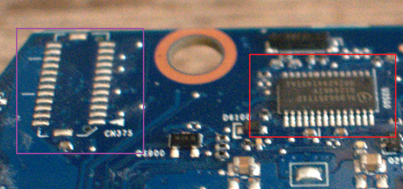
o sniff the LPC bus, we need to connect seven wires in total. Clock, LFRAME, LAD0, LAD1, LAD2, LAD3
and ground. I didn’t have any logic probes fine enough to clamp onto
the 0.65mm pitch pins, so I would have had to solder fly leads directly
to the TPM chip. I noticed that there is an unpopulated header to the
left of the TPM chip (the purple box above), so decided to poke at this
with a multimeter in continuity mode just in case its a debug header
attached to the LPC bus. Thankfully, this was indeed a header with LPC
bus connectivity. I decided to solder the fly leads to these pads,
instead of directly to the TPM. The reasoning was pretty simple, the
header uses a bigger pitch and is easier to solder. If you don’t have a
LPC debug header somewhere on the board, then either take care and
solder directly to the TPM (more on this later!) or pick up some probes
that can handle a TSSOP28 package.
At this point I had physical connectivity to the bus, so the next step was to connect something to read out the LPC messages.
I picked up a DSLogic Plus 16 channel logic analyzer and wired it up. Given the LPC bus clock runs at 33MHZ, I decided to sample at 100MHZ, which the DSLogic can happily do across multiple channels. Booting the laptop and running the logic analyzer, I see valid LPC data that I can decode using DSView’s LPC decoder. DSView uses libsigrokdecode, so this should be same same in Pulseview.
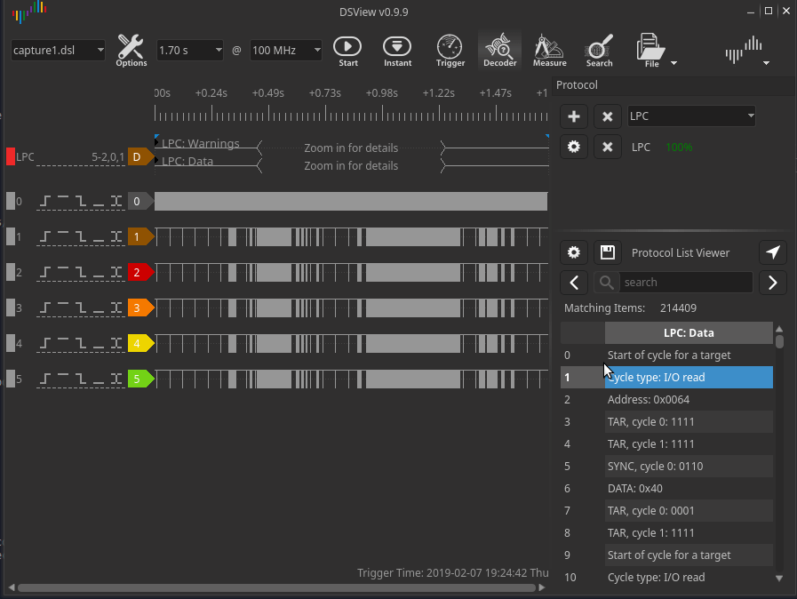
There are two problems I had to tackle. The first being the decoder reported the TPM messages as reserved
and didn’t decode them correctly, the second is that the logic analyzer
does not have enough storage to capture the complete boot process, so I
was only seeing a snapshot of what was happening at boot time.
DSLogic’s run-length-encoding meant that I could happily capture the
entire boot process as long as I didn’t capture the clock signal. But
without the clock signal, the decoders wouldn’t work and I’d have to
decode everything by hand. Given the large number of LPC messages,
decoding by hand wasn’t going to happen!
Fixing the LPC decoder
The TPM LPC transactions use a specific START field
(0101), so the decoder needed to be modified to understand this. I won’t
bore you with the details on fixing the decoder, instead I’ve sent a pull request for the DSView repository and emailed the Sigrok dev mailing list with a patch.
Splicing in a clock
The next issue was the lack of clock. My solution was hacky. Don’t do it this way, get a better logic analyzer instead.
So with a single channel, I can capture 100MHZ in stream mode
(meaning I can grab a full ten seconds of clock). My plan was to capture
the 5 signals I need using a 10 second capture during boot, then
capture 10 seconds worth of clock (multiple times, so I have a few tries
to deal with phasing issues) and then mash these two together with
reckless abandon. Again, you probably don’t want to do this and instead
use a logic analyzer with a sufficient sample depth (6 channels @ 100MHZ
for 10 seconds). Combining these was a case of unzipping the capture
file, adding in the new data and modifying the header file to add in the additional probe.
The end result was a huge number of LPC messages and a gross feeling inside.
LA summary
You can indeed extract BitLocker keys with a logic analyzer. Don’t do what I did though, use a logic analyzer with a greater sample depth. Not being able to trust your tools is the worst.
TPM2.0
TPM2.0 devices support command and response parameter encryption, which would prevent the sniffing attacks. Windows doesn’t configure this though, so the same attack a TPM1.2 device works against TPM2.0 devices.
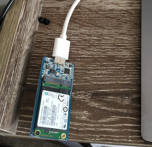
Originally, I didn’t want to use an FPGA for this, but they’re cheap and the LA approach above isn’t particularly pleasant. The sniffing for the TPM2.0 example was done using a Lattice ICEStick. This also had the bonus of giving me something I didn’t have to second-guess when we need to bust this out during a penetration testing or red team engagement. Onward with the FPGA! The following attack was performed against a Surface Pro 3.
LPC Sniffer Code
I used https://github.com/lynxis/lpc_sniffer with a few changes. The ICEStick will read the LPC messages and send the data back over UART. Fast-opto mode needs to be enabled on the second interface of the ICEStick’s FTDI chip.
I tweaked the code base to look for the TPM specific start field. I
ran into issues with the ring buffer overflowing (too many LPC
messages), so I modified the code base to bump the baud rate and only
record messages with address 0x00000024. This seemed to solve the overflow issues and let me capture all the 0x00000024
addressed data during boot. If you’re using an ICEStick with this code
base, keep your eyes peeled for the green overflow LED. If the ring
buffer starts overflowing, then you will get incomplete data.
The sniffer code is available here: https://github.com/denandz/lpc_sniffer_tpm
Wiring
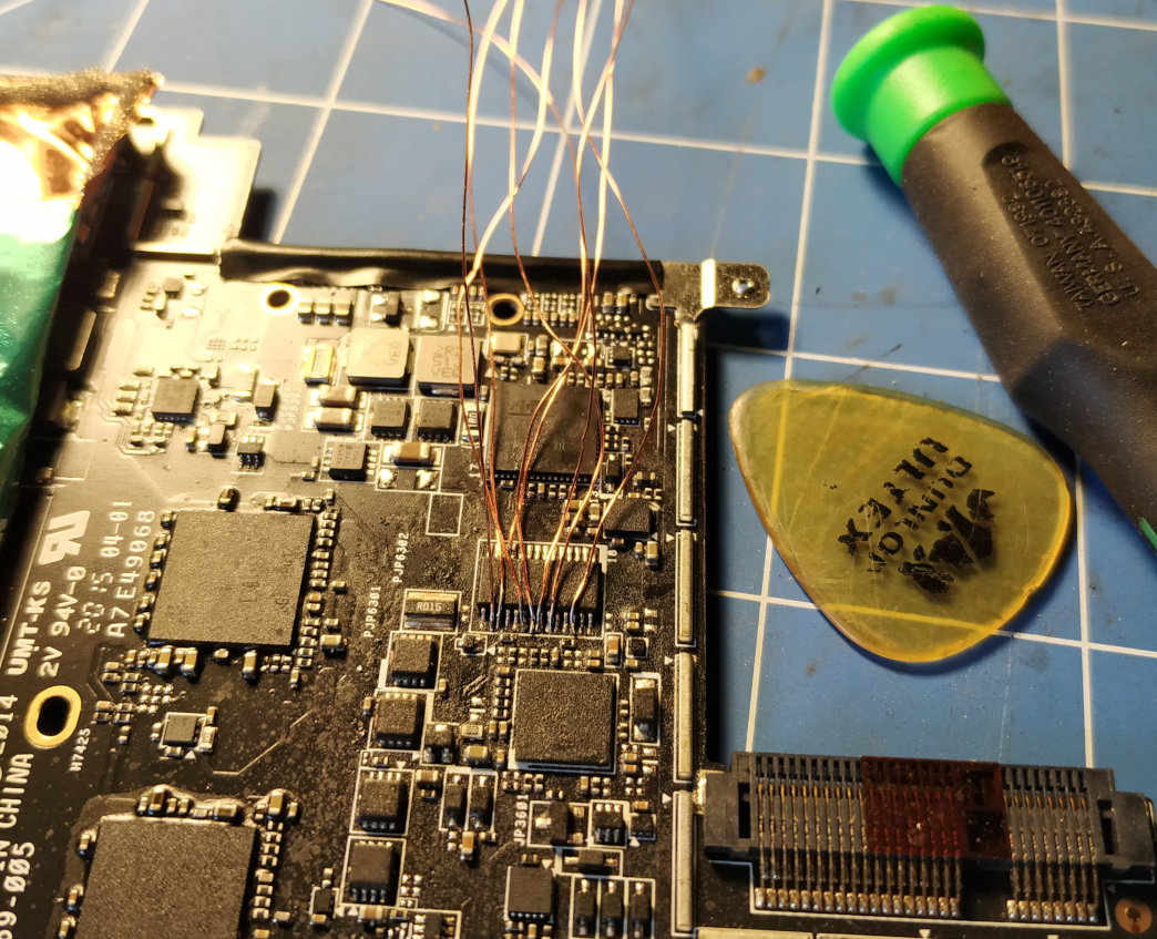
Wiring up the Surface Pro 3 was probably the least pleasant part of this entire project. Luckily, my device already had a faulty screen, so I didn’t feel too bad when I destroyed it further. You can follow the tear-down on iFixit if you’re trying this yourself. My advice? Go slow, use liberal application of the heat gun and do not pry. If I had to do this again I think I could get the screen out without damaging it. I suppose it’s a case of practice and not cracking under pressure.
After removing the logic board, the TPM chip is on the underside, an Infineon SLB9665TT2.0

I opted to solder some fly leads directly to the TPM chip. There are a
bunch of various unpopulated headers kicking around on this board, but
they’re all fine pitch so figured I might as well try attaching to the
chip directly. The Surface was then reassembled with the fly leads
routed outside the case. I soldered fly leads to the GND, LCLK, LFRAME#, LRESET# and LAD[0:3] pins. I tinned the ends and labeled the leads using masking tape.
After wiring and flashing the FPGA, the VMK was retrieved by issuing the following command, then powering on the Surface:
sudo python3 parse/read_serial.py /dev/ttyUSB1 | tee log1The data returned from the FPGA is structured as b'[32 bit address][8 bit data][read (00) or write (02)]'.
The following one-liner was used to retrieve the VMK:
doi@buzdovan:~/tools/lpc_sniffer_tpm$ cut -f 2 -d\' log1 | grep '24..00$'  \
> | perl -pe 's/.{8}(..)..\n/$1/' | grep -Po "2c0000000100000003200000(..){32}"
2c00000001000000032000009a126146b5b285c93f7c4bcd372f91d0181fe7eddc44e588459ebdb244d97baa
In this case, the VMK was 9a126146b5b285c93f7c4bcd372f91d0181fe7eddc44e588459ebdb244d97baa
Decrypting the Drive
Drive decryption was achieved by using the Dislocker code base to decrypt the FVEK, then mounting the drive. In the case of the Surface Pro 3, an image was taken of the drive first:
The encrypted FVEK, MAC and nonce was retrieved using the dislocker-metadata command:doi@buzdovan:~/src/dislocker-0.7.1/src$ sudo dd status=progress if=/dev/sda of=surface_pro.img bs=8M 127934660608 bytes (128 GB, 119 GiB) copied, 474 s, 270 MB/s 15263+1 records in 15263+1 records out 128035676160 bytes (128 GB, 119 GiB) copied, 475.489 s, 269 MB/s
Defense
Enabling BitLocker with a TPM+PIN protector should mitigate this
vulnerability, however user’s will be required to enter a PIN at boot.
Smart cards or USB keys used as an additional pre-boot authentication in
 addition to the TPM should mitigate this issue as well. I’d need to
take a closer look at the different protector modes to be able to say
for certain, maybe some future work.

Microsoft detail BitLocker countermeasures here, as well as going into protecting against different attacker types. I suggest reading the section on attacker countermeasures here.

As the system boots with no key material required from the user,
there are a myriad of ways to attempt to retrieve the BitLocker key. DMA
 attacks come to mind, I wonder if there are any protections for
physically lifting the TPM chip and talking to it directly? Even if
request and response parameter encryption is enabled, vectors for
retrieving the keys from the TPM likely still exist and enabling
additional protectors (such as PIN codes) would be the way to go.

I ended up sending the TPM2.0 attack details and sniffer source to
MSRC, their advice was to enable additional pre-boot authentication if
you’re worried about this attack:


We have completed our investigation, and the behavior that you
reported is something we’re aware of. We don’t expect any further action
 on this item from MSRC and will be closing out the case.

There is nothing new or novel, nor is this unique to Surface, it

applies to all dTPMs, both 1.2 & 2.0. Some fTPM resist this attack

(MitM dTPM), but you could just do MitM on the memory (or freeze it).